MorphoNetJ Plugin Advanced Help
This section contains advanced help for users of the MorphoNet FIJI plugin, particularly how to convert 3D and 4D images into meshes in an optimal fashion.
Who is this help for ?
If you are a user of the MorphoNet FIJI plugin trying to upload data to MorphoNet, and that your data looks wrong using the default parameters we provide, this section will help you understand how to obtain higher quality data using our plugin.
An example
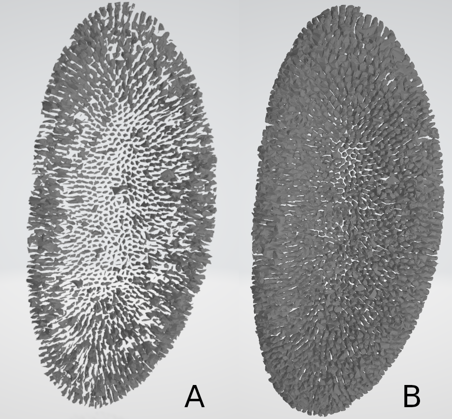
Let's take an example : Using this image (see below) of a drosophilia melanogaster embryo, and the base parameters for 3D image-to-mesh conversion, we obtain a very poor mesh (see below).
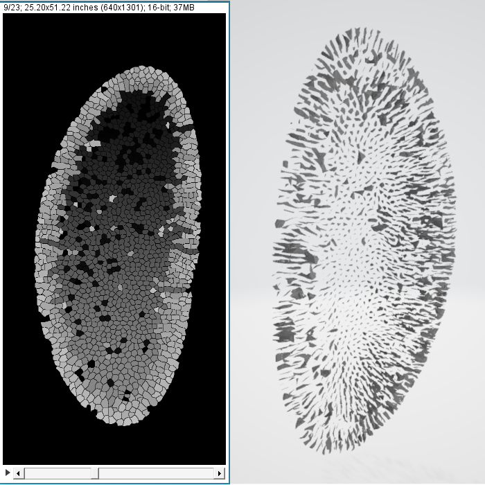
This result can be explained in several ways : - First off, we can see that the input image is high-resolution for this axes X and Y (width and height), but very low resolution for the axis Z (depth), as there are only 23 slices. If we use a strong downscaling factor for all dimensions, we will end up with a image with very low resolution in the Z axis (depth), which will then result in a low-resolution, maybe even outright unusable mesh. One way to fix this is to use a different downscaling factor for the width and height than for the depth. In the next example, we use a downscaling factor of 3 for width and height, and a downscaling of 1 (no downscaling) for the depth. All of a sudden, the resulting mesh looks way better. However, it is still not perfect, and we would like to get a better-quality mesh, while maintaining a managable file size.
- Secondly, we can change the advanced parameters for the operations that are applied on our mesh. These operations are : Smoothing (we can change the passband, and the number of iterations), Quadric clustering (we can change the number of divisions), and Decimation (we can change the reduction, and the threshold for auto-calculation of the decimation). We will explain these in more detail in a later part. For this example, we do not actually need to smooth the mesh, as its shape does not encourage this step, and the decimation causes too many atrefacts. we will disable these options, and we will make the decimation step a little less "agressive", by lowering the reduction from 0.8 to 0.4.
Using these slight changes, we went from a mesh that was unusable, to a mesh of high fidelity and relatively small size storage-wise (see end result below). However, considering for this case that we have only one time step, and that the data is fairly big, we will make sure to check the Split large mesh option with a threshold of 60000 vertices to cut it in several files, insuring a smoother loading experience on MorphoNet.
The main options menu
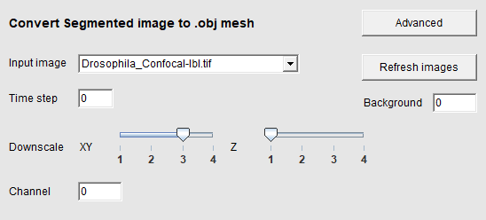
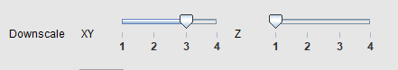
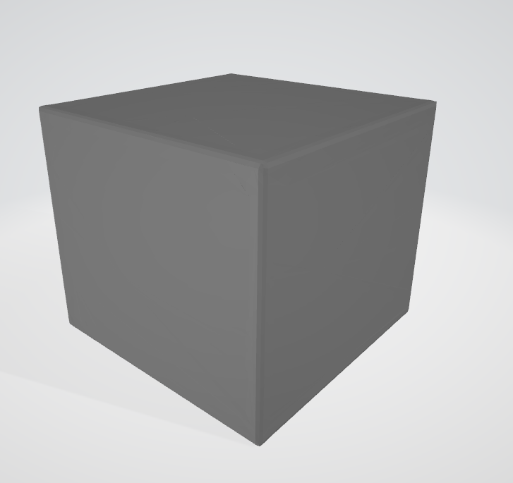
In the main options menu, the only options that will change the appereance of our resulting mesh are the Downscaling sliders. The rest are for MorphoNet and the upload parameters. Just make sure that the Background option has the correct value corresponding to the background color of your image. Otherwise you might have meshes that look like big squares, like this for example.
The Downscaling sliders allow you to downscale your original images before they are converted to meshes. It is useful to create smaller meshes that will be faster to load, lighter to save to storage, and will still be of high enough quality to view on MorphoNet, that does not require too high quality meshes. They will also be generated quicker. There are two sliders, one to rescale the Width and Height (axis X and Y), and another one for the Depth (axis Z). This difference is because in a lot of 3D images, the depth resolution is far lower than the rest of the images. This allows us to have a non-uniform rescaling, and to have a final image that has an interesting resolution to be converted in meshes; an image that has too low of a resolution in a dimension or more will yield unusable meshes, as shown in the previous example.
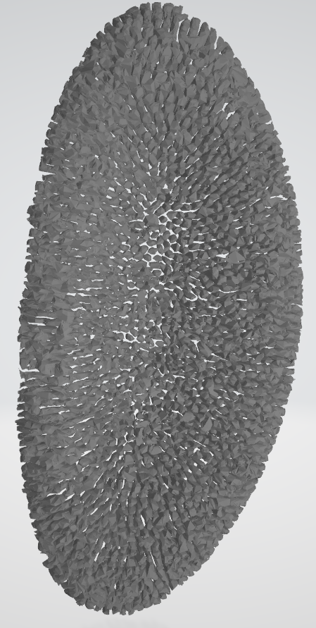
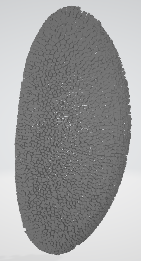
A low downscaling factor (1 or close to 1) will yield higher resolution meshes that those created with a high downscaling factor (see below : first mesh has factor of 1 in figure A, second has a factor of 4 in figure B)
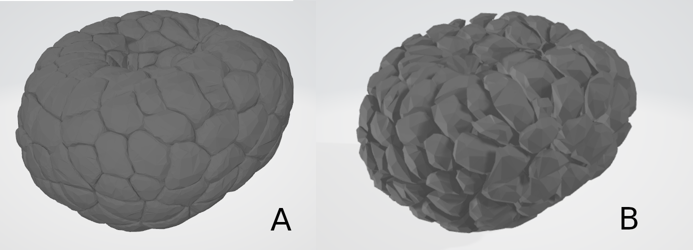
Below, we see the difference between a mesh with a low depth resolution, generated with a downscaling factor of 3 on all dimensions (figure A), then one generated with a factor of 3 for width and height, and a factor of 1 in depth (figure B).
Experiment with these values, to find the best combination for your images. As a rule of thumb, we try to make it so the downscaled images have a resolution that is roughly between 256 and 100 pixels in any given dimension.
The advanced menu
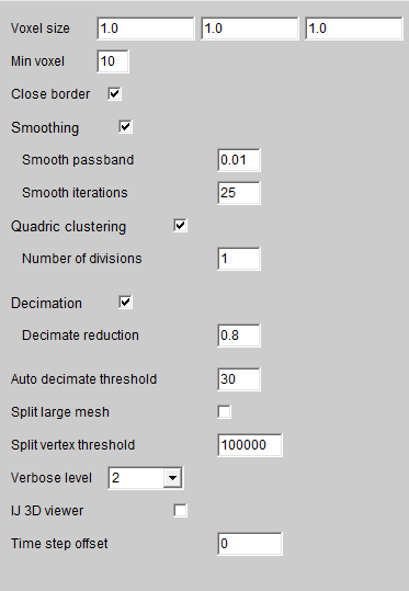
The advanced menu is the main way to change the appearence of the converted meshes apart from the downscaling factors. Here we can manage if and how the operations of Smoothing, Quadric clustering and Decimation happen. In this section we will detail how these parameters influence the final result, and when and how you should change the default parameters. Please know that each operation is applied element per element (cell by cell in most cases) and not on the whole mesh at the end of the generation. For this reason, not all elements may be affected by the operations in the same manner, mainly depending on the sizes of the elements. Each sub-element is called a sub-mesh.
Smoothing
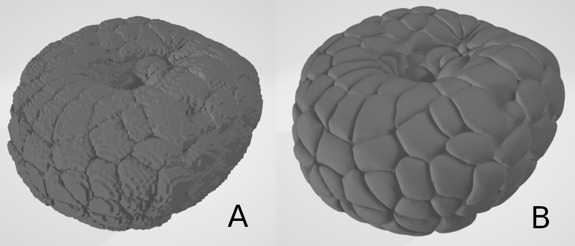
Smoothing is the first operation executed on the resulting meshes. Because the algorithm used to convert 3D images to meshes is Marching cubes, the resulting meshes without any pre-processing have a "staircase effect". The smoothing step aims to remove this effect and give a smoother surface to meshes. Below you can see a generated mesh before (fig. A) and after smoothing (fig. B). Each operation is enabled by default, and can be disabled by unchecking the corresponding checkbox.
There are two parameters to the smoothing operation : the smooth passband, and the number of iterations.
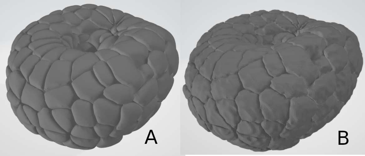
- Smooth passband : Must be a floating point number between 0 and 2. Lower values produce more smoothing. Below you can see the difference between a mesh generated with only smoothing and a passband of 0.01 (fig. A), and the same with just smoothing and a passband of 0.3 (fig. B). As you can see, only 0.3 already makes the "staircase effect" more visible. Unless you know what you are doing, we recommend you do not tinker with this parameter too much.
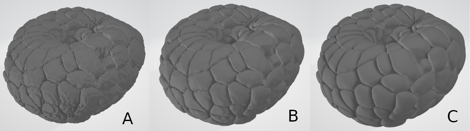
- Smooth iterations : The number of smoothing operations executed on the mesh. 10 to 20 is usually a good number, and you want to be careful not to smooth with too few iterations, as the first ones are the ones that modify the mesh the most. Down here is an example of a mesh with 5 iterations (A), 10 iterations (B) and 25 iterations (C). Once again, unless you know what you are doing or are looking for a particular result, we do not recommend that you change this parameter too much.
As you can see, the smoothing operation does a lot for the general shape of the generated meshes. though it makes them bigger in size, it also gives them a more "realistic" shape, making the "staircase" effect less visible. You can however disable it or make it less strong to preserve the original shape of the elements, which can be useful for some images that are large and with a high density of small elements (like the drosophilia melanogaster image given in the example part of this tutorial).
Quadric clustering
The quadric clustering operation aims to recude the number of triangles in a given mesh, while retaining a good approximation of the original geometry. There is one parameter you can choose, and it is the number of spatial subdivisions
- Number of divisions : without going into detail, the algorithm uses subdivisions of the space to recompute the vertices. A higher number of divisions roughly equates to a higher number of vertices, but the difference is small. Unless you know what you are doing, we recommend that you do not change this parameter. However, enabling or disabling Quadric clustering yields large differences.
Down below you can see the same mesh, generated without quadric clustering (A), with quadric clustering and 1 division (B), and with 10 divisions (C).
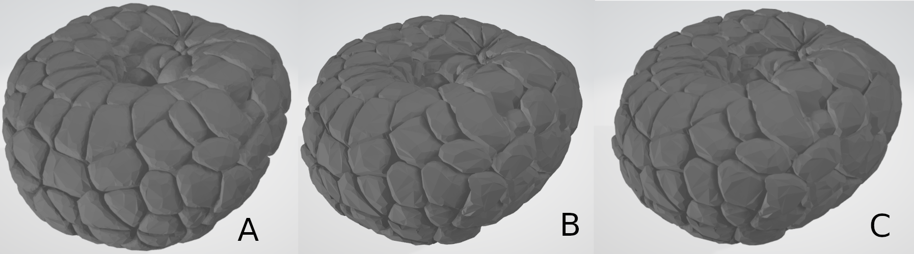
As you can see, the differences between Quadric clustering disabled and enabled may look minor, but the file is over 2 times smaller in size. The difference with 1 division and 20 divisions is however, barly noticeable visually and size-wise. The difference will however be higher for meshes with a high amount of small elements, like the mesh generated in the example part of this tutorial. Playing around with this option will allow you to find the balance between file size, amount of detail and shape preservation : if your generated mesh looks nothing like you expect it to, you might want to disable this option. if your resulting file is too big, you may want to enable it to have a smoother loading of MorphoNet.
Decimation
The final operation executed on the meshes in the decimation. This step also aims to reduce the amount of triangles in a mesh, while preserving the original geometry, but with a different algorithm than the Quadric clustering step. The option is enabled by default, and you can disable it or re-enable it by checking the according checkbox. The parameters you can modify to change this step is the decimation reduction and the auto decimation threshold.
- Decimation reduction : This parameter, a floating point number between 0 and 1, corresponds to a percentage of the size you want to end up with. For instance, with a reduction of 0.9, the filter will try to reduce the data to 10% of its original size. In other words, a higher reduction will yield a smaller mesh, in size and with less detail. Down below you can see the same mesh generated with a reduction of 0.1 (A), a reduction of 0.5 (B), and a reduction of 0.9 (C).
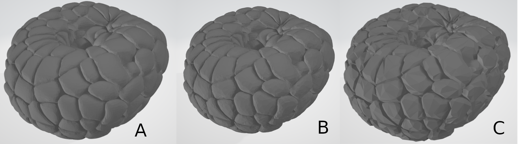
As you can see, with higher reduction values, the meshes will be smaller in size, and be less detailed.
- Auto decimation threshold : This option tries to compute the best reduction value automatically, iterating the operation until the amount of vertices generated per element is at least higher than the given threshold. With this option, the decimation step will be repeated if it outputs a sub-mesh with a number of vertices lower than the given threshold, with a lower reduction value to try to generate a sub-mesh with more vertices. this step can be repeated until the reduction value drops to 0, in which case if there are still not enough vertices in the generated sub-mesh, the decimation step will be skipped. This option can be effectively disabled by setting the threshold to 0. This will make it so the decimation reduction value may be different for all sub-meshes of your generated meshes, and tries to help you out in generating meshes with enough detail. It is a very useful option when you have an image with elements of various sizes, to preserve the details on smaller elements. A higher threshold will mean that the decimation operation will be less strong overall (and it may slow down the execution somewhat). for more control on the decimation reduction parameter, you may disable this option.
Other options
The rest of the advanced menu option has no influence on the appearance of your generated meshes. One other noteworthy option however is the split large mesh option, divided in the split large mesh checkbox and the split vertex threshold text field. This option allows you to split your meshes in several sub meshes, to try to have a smoother loading experience on MorphoNet. On MorphoNet, a mesh is loaded all at once, which means that a single file is first loaded in memory, and only displayed once loaded entierly. This means that for large files, you may have to wait a couple of seconds or more to have your data displayed. To help with this, the splitting of your file makes it so it loads in chunks, giving you a more progressive, smooth loading. The option can be enabled or disabled with the checkbox, and the threshold field allows you to manage the number of splits. when the file is written, every time we reach a number of vertices equal or higher to the thresold, the mesh will be split upon reaching the end of the current submesh. In other words, the lower the threshold, the higher the number of generated files. This option is mainly useful on large datasets with one or few time steps, and should not be overused with smaller datasets.
References
-
The drosophilia melanogaster data is from Real-Time Three-Dimensional Cell Segmentation in Large-Scale Microscopy Data of Developing Embryos , courtesy of Johannes Stegmaier (RWTH Aachen University)
-
The ascidian embyro data shown is from Contact area–dependent cell communication and the morphological invariance of ascidian embryogenesis